
Hi everybody... I think that this is a really cool tip... enjoy the video...
Thursday, December 13, 2007
Monday, December 10, 2007
New Stormwater Design and Analysis Extensions for Civil 3D!!!
Hi everyone.... Autodesk is continuously coming out with solutions and applications to improve Civil 3D 2008. At this time, Autodesk recently concluded the acquisition of Intelisolve’s Business. Intelisolve is a highly respected provider of Hydraulics and Hydrology Design and Analysis Software for Civil Engineering. This acquisition adds important technology to our civil engineering solution and will help our customers address a critical part of their workflow.
The acquired technology will be delivered as three extensions for AutoCAD Civil 3D subscribers:
- Hydraflow Storm Sewers Extension for storm sewer analysis and design.
- Hydraflow Hydrographs Extension for pond design.
- Hydraflow Express Extension for culvert, channel, and inlet analysis.
You can find out some highlights in AutoCAD Civil 3D Stormwater Website to provide details on the functionality of the extensions.
The three extensions are available for download by AutoCAD Civil 3D 2008 Subscription Users from the Autodesk Subscription Center.
Wednesday, December 5, 2007
Probably this could help you!!!
Hi Everybody... These are some videos that I hope they will help you to work or figure out some things...
Survey and Civil 3D - Working with Survey Link
Survey and Civil 3D - Working with Survey Link
Creating a Distance with crows feet Label
Thursday, November 1, 2007
Survey Equipment Partners and More…
Autodesk works closely with a number of suppliers of survey equipment as well as developers of software add-ons for Civil 3D. (To go to the links please click on the logos)

Leica X-change provides a seamless link between Leica System 1200 surveying equipment and the AutoCAD Civil 3D environment.
 Trimble Link for AutoCAD Civil 3D enables you to transfer survey and design data between the Civil 3D database and Trimble field systems including the TSC1, TSCe, ACU Controller, Trimble CU Controller, Geodimeter CU600, and supported Nikon instruments. It further supports the use of Trimble site controller systems.

Carlson Connect is an add-on to AutoCAD Civil 3D 2008 that offers a collection of routines for transferring and converting data between Civil 3D 2008 and several popular data collectors. Carlson Connect runs inside Civil 3D 2008 and uses the current project data and design environment. Carlson Connect is a free utility to any Civil 3D 2008 user and can be downloaded.
Find more information about the availability of trird-party applications compatible with AutoCAD Civil 3D software in Partner Products & Services .
Leica X-change provides a seamless link between Leica System 1200 surveying equipment and the AutoCAD Civil 3D environment.
Trimble Link for AutoCAD Civil 3D enables you to transfer survey and design data between the Civil 3D database and Trimble field systems including the TSC1, TSCe, ACU Controller, Trimble CU Controller, Geodimeter CU600, and supported Nikon instruments. It further supports the use of Trimble site controller systems. Carlson Connect is an add-on to AutoCAD Civil 3D 2008 that offers a collection of routines for transferring and converting data between Civil 3D 2008 and several popular data collectors. Carlson Connect runs inside Civil 3D 2008 and uses the current project data and design environment. Carlson Connect is a free utility to any Civil 3D 2008 user and can be downloaded.
Find more information about the availability of trird-party applications compatible with AutoCAD Civil 3D software in Partner Products & Services .
Wednesday, October 31, 2007
Civil 3D Does Survey - Really!!!
Hello everybody, Check this out. It is a courtesy document from a Users Group out west...
The survey primer that was developed by a users group out west. Yes, surveyors are really using it. The doc touches on setting up the survey database and accessing the new survey link extension. Civil 3D is catching on with surveyors, even the small, survey-only firms. Why? There are several good reasons.
1. Civil 3D is technically much improved over previous versions. The newly released survey link closes the last big feature gap. The survey database provides for on-the-fly, true coordinate transformations – which is a big differentiator when surveyors do a lot of GPS work. Autodesk will be documenting customer experiences for articles in survey publications starting in December. More on this as they come out.
2. The surveyors’ customers want existing surface models for accuracy, productivity and liability reasons. They don’t want to have to re-process survey data (e.g. point or fieldbook files) to create their models.
3. Unlike some other apps, Civil 3D is built on Map. This provides important functionality in terms of coordinate system support, drawing & GIS conversion, database attachments, topology analysis, image attachment – important if the surveyor is involved in environmental work.
The bottom line is that, while we may not be at the price point of some standalone survey apps, we do provide considerable value for the money. It’s the kind of value that can open up new revenue opportunities or be a competitive differentiator at a time when the market is changing.
Ray Metzger, PE
Southern Region Civil Territory Manager
Autodesk, Inc.
Survey and Civil 3D
First start by setting up your survey database.
Take note that every time you create a survey network a folder and associated files are created outside of the actual drawing. Therefore, all folders that are created are constantly viewable whether or not your drawing is open.
To setup the survey data base first go to
Survey > Open Survey Tool Space
The image below is before you open. The image next to it is after you open the survey tool space.
 This controls where everything looks in the Survey tab. At the top are two buttons with disks and arrows, those are import and export settings buttons. You can bring a presetup setting into this just by hitting one of those buttons.
Next let’s expand the Survey Database. All that should be there is Example. If you right click on the title “Survey Database” and select “New Local Survey Database” a box comes up and asks for a name to be given to your database. This box also creates a folder at the same time for your survey database and associated files with this folder. I chose to create one called “help me”. After you create a local survey database and expand the selection this is what will be seen below.
 To set default settings before importing a Field book file (*.FBK) or any other survey type of file right click on “Help Me” and chose “edit Survey data base settings.
The following box appears.
 Review all items in this box before importing anything. Hit Ok when you’re done.
Before you do any importing we need to setup the other 2 parts of the survey database.
For Equipment Database, if you expand what is there you should see example. Go ahead and create a new one by right clicking on the heading “equipment database” and select new…
Give it a name that is the data collectors’ name that was used on the job. Now we will setup what equipment was used to perform the survey on the job site. You can set several of these up if you have several different Data Collectors or equipment items used in the office.
 As you see I created E07-500, granted it’s not my data collector’s name but it’s a name. Right click on what you just created and again chose new…
 This box controls tells Civil 3D what equipment was used and it’s setting. Change the settings to what your equipment is.
Lastly let’s setup the Figure database. Again right click on “Figure Prefix Database”, chose new… Enter your job’s name or number here. And again right click on what you just created and chose new…
 This box controls the linework as it comes in from the field book. You’ll want to create one item per one item of line work. So you’ll need to make one for each item that is linework within you field book file such as Lots, bldgs, Edge of Pavement, ditch lines, break lines, Edge of gravel, curbs, fences and bridges. These will stay with every job you make, you only have to make them once usually. So you can add to them. If you chose the breakline box then the field book will create them as a breakline which is useable in a surface via the prospector tab. If they are lot lines, check the lot line box. It is important to put each item on a Unique layer, not 0. Style and site are variable. If you have already created styles, under the settings tab, survey styles section then they will be available here. If not you can change any of these at a later date. But this information in this box controls the initial import of the field book, not after it is imported.
Once your done with that, you’re ready to import a field book.
Go into the Survey Database where you created a Database, and expand what you created so that you see Networks, Network Groups, Figures, Figure groups, etc… Right click on Networks and chose New. Give it a name, like a date of your survey or maybe just topo. Expand the newly created network.
 Note that it has a place to either create manually the control points, directions, traverses and setups. Or you can import by right clicking on what you created, mine is topo 7-10-07. If I right click I get a huge pull down menu. Too import a field book I chose Import field book, browse to my field book and hit open. The following box appears
 Change all the stuff needed to go with your default settings you just created then hit OK.
After you hit OK your drawing is magically drawn, well you can watch Civil 3D create all the lines in the world. It’s pretty neat.
Now that the lines are created we may need to manipulate what is there. To edit control points, expand your control points, select the item to be edited then right click and chose edit.
To edit directions, again, expand and right click over the item and chose edit.
To edit Setups, expand the setups, right click and chose edit observations or edit depending on what you need.
Each edit brings up the panorama window. After making your changes, hit the save button next to the green check before hitting the green check to make sure your changes are saved.
 You can add traverses by right clicking and selecting New.. The following box appears. Fill in what you need and go from there.
 At this point running through the tutorials on this is very helpful on how this works, it’s simple but we just don’t have enough time to run through everything.
Ok enough with Field books. What if you don’t have a Field book. How do you import in your *.job or *.RAW file.
Just the other day Autodesk came out with the addon for the good old Survey Link pull down.
Login to your subscription center and it’s at the very bottom. Install the *.MSI file, then read/print the readme file to figure out how to place it on your pull down via the CUI interface. It’s very simple and straight forward.
Once it’s there this is the box that comes up when you do select the Survey Link from your Survey Menu pull down.
 Look familiar? It’s the same one from LDT.
And it works the same way.
The survey primer that was developed by a users group out west. Yes, surveyors are really using it. The doc touches on setting up the survey database and accessing the new survey link extension. Civil 3D is catching on with surveyors, even the small, survey-only firms. Why? There are several good reasons.
1. Civil 3D is technically much improved over previous versions. The newly released survey link closes the last big feature gap. The survey database provides for on-the-fly, true coordinate transformations – which is a big differentiator when surveyors do a lot of GPS work. Autodesk will be documenting customer experiences for articles in survey publications starting in December. More on this as they come out.
2. The surveyors’ customers want existing surface models for accuracy, productivity and liability reasons. They don’t want to have to re-process survey data (e.g. point or fieldbook files) to create their models.
3. Unlike some other apps, Civil 3D is built on Map. This provides important functionality in terms of coordinate system support, drawing & GIS conversion, database attachments, topology analysis, image attachment – important if the surveyor is involved in environmental work.
The bottom line is that, while we may not be at the price point of some standalone survey apps, we do provide considerable value for the money. It’s the kind of value that can open up new revenue opportunities or be a competitive differentiator at a time when the market is changing.
Ray Metzger, PE
Southern Region Civil Territory Manager
Autodesk, Inc.
Survey and Civil 3D
First start by setting up your survey database.
Take note that every time you create a survey network a folder and associated files are created outside of the actual drawing. Therefore, all folders that are created are constantly viewable whether or not your drawing is open.
To setup the survey data base first go to
Survey > Open Survey Tool Space
The image below is before you open. The image next to it is after you open the survey tool space.
 First off, where does the survey tab store all this great info it creates? See that icon below the Learn More at the top? That is the control settings for the survey tab. Review these before creating any Survey databases.
This controls where everything looks in the Survey tab. At the top are two buttons with disks and arrows, those are import and export settings buttons. You can bring a presetup setting into this just by hitting one of those buttons.Next let’s expand the Survey Database. All that should be there is Example. If you right click on the title “Survey Database” and select “New Local Survey Database” a box comes up and asks for a name to be given to your database. This box also creates a folder at the same time for your survey database and associated files with this folder. I chose to create one called “help me”. After you create a local survey database and expand the selection this is what will be seen below.
To set default settings before importing a Field book file (*.FBK) or any other survey type of file right click on “Help Me” and chose “edit Survey data base settings.The following box appears.
Review all items in this box before importing anything. Hit Ok when you’re done.Before you do any importing we need to setup the other 2 parts of the survey database.
For Equipment Database, if you expand what is there you should see example. Go ahead and create a new one by right clicking on the heading “equipment database” and select new…
Give it a name that is the data collectors’ name that was used on the job. Now we will setup what equipment was used to perform the survey on the job site. You can set several of these up if you have several different Data Collectors or equipment items used in the office.
As you see I created E07-500, granted it’s not my data collector’s name but it’s a name. Right click on what you just created and again chose new…This box controls tells Civil 3D what equipment was used and it’s setting. Change the settings to what your equipment is.Lastly let’s setup the Figure database. Again right click on “Figure Prefix Database”, chose new… Enter your job’s name or number here. And again right click on what you just created and chose new…
This box controls the linework as it comes in from the field book. You’ll want to create one item per one item of line work. So you’ll need to make one for each item that is linework within you field book file such as Lots, bldgs, Edge of Pavement, ditch lines, break lines, Edge of gravel, curbs, fences and bridges. These will stay with every job you make, you only have to make them once usually. So you can add to them. If you chose the breakline box then the field book will create them as a breakline which is useable in a surface via the prospector tab. If they are lot lines, check the lot line box. It is important to put each item on a Unique layer, not 0. Style and site are variable. If you have already created styles, under the settings tab, survey styles section then they will be available here. If not you can change any of these at a later date. But this information in this box controls the initial import of the field book, not after it is imported.Once your done with that, you’re ready to import a field book.
Go into the Survey Database where you created a Database, and expand what you created so that you see Networks, Network Groups, Figures, Figure groups, etc… Right click on Networks and chose New. Give it a name, like a date of your survey or maybe just topo. Expand the newly created network.
Note that it has a place to either create manually the control points, directions, traverses and setups. Or you can import by right clicking on what you created, mine is topo 7-10-07. If I right click I get a huge pull down menu. Too import a field book I chose Import field book, browse to my field book and hit open. The following box appearsChange all the stuff needed to go with your default settings you just created then hit OK.After you hit OK your drawing is magically drawn, well you can watch Civil 3D create all the lines in the world. It’s pretty neat.
Now that the lines are created we may need to manipulate what is there. To edit control points, expand your control points, select the item to be edited then right click and chose edit.
To edit directions, again, expand and right click over the item and chose edit.
To edit Setups, expand the setups, right click and chose edit observations or edit depending on what you need.
Each edit brings up the panorama window. After making your changes, hit the save button next to the green check before hitting the green check to make sure your changes are saved.
You can add traverses by right clicking and selecting New.. The following box appears. Fill in what you need and go from there.At this point running through the tutorials on this is very helpful on how this works, it’s simple but we just don’t have enough time to run through everything.Ok enough with Field books. What if you don’t have a Field book. How do you import in your *.job or *.RAW file.
Just the other day Autodesk came out with the addon for the good old Survey Link pull down.
Login to your subscription center and it’s at the very bottom. Install the *.MSI file, then read/print the readme file to figure out how to place it on your pull down via the CUI interface. It’s very simple and straight forward.
Once it’s there this is the box that comes up when you do select the Survey Link from your Survey Menu pull down.
Look familiar? It’s the same one from LDT.And it works the same way.
Friday, October 19, 2007
AutoCAD Civil 3D 2008 Survey Link Extension!!!
Hi everybody, this is Good News for Surveyor Users ... AutoCAD Civil 3D 2008 Survey Link is a downloadable extension for AutoCAD Civil 3D 2008 software customers on Autodesk Subscription. This extension requires AutoCAD Civil 3D 2008 Service Pack (SP) 2 and is targeted to be available worldwide for all AutoCAD Civil 3D subscribers.
Survey Link allows proprietary raw survey data to be converted into an Autodesk field book (.FBK) and imported into Autodesk Civil 3D 2008, further enhancing the survey functionality in AutoCAD Civil 3D 2008 software.
Actions:
1. Download AutoCAD Civil 3D 2008 SP2.
2. Donwload the Survey Link extension (Please remember to refer to the readme file for the installation).
Important SP2 Now Available!!!
Hello everybody... Good news for all of us Service Pack (SP2) for AutoCAD Civil 3D 2008 and AutoCAD Land Desktop 2008 software are available for customer download. These are both general maintenance service packs. Please refer to the Readme files prior to applying SP2 for information on installation and resolved issues.
- Download this files now...
Wednesday, October 3, 2007
Collaboration and Publishing to Google Earth!!!
Hi everyone... At this time I will like to share this video which is a real project that is located in Central American where you can see how you can do presentations incorporating all the tools that Civil 3D have to offer...
Unfortunately the audio is in Spanish, sorry about that... Hope that you enjoy it anyhow...!!!
Unfortunately the audio is in Spanish, sorry about that... Hope that you enjoy it anyhow...!!!
Wednesday, September 26, 2007
Alternative Design and Resources...
Hi everybody... For some of you who are looking to learn how you can create an Intersection or a Complex Corridor, I saw last week (September 21, 2007) a really interesting webcast call Alternative Road Design Tactics Using AutoCAD Civil 3D 2008. In this webcast they show a different way to create Intersections using just alignments. At the same time I invite you to go and look under Useful Links!!! on this page, so you can check and have access to all the information that Autodesk has available to you for free. You will find places where you can download lots of information and it will make your learning process more easier...
So go and check it out:
AutoCAD Civil 3D - Resource Center
Civil 3D Webcasts - General Civil 3D
Civil 3D Webcasts - Road & Transportation Design
Civil 3D Webcasts - Production Drafting
So go and check it out:
AutoCAD Civil 3D - Resource Center
Civil 3D Webcasts - General Civil 3D
Civil 3D Webcasts - Road & Transportation Design
Civil 3D Webcasts - Production Drafting
Tuesday, September 11, 2007
Point Label Styles Issue...!!!
Hi everybody … I noticed a point label issue in some of the Civil 3D Drawing Templates, I think that it is really important to fix it because some of you probably use those as a base to create your own template or you just work directly with them like I do, whichever will be your case it’s better to be aware of, and also be able to make it work. As everybody knows Civil 3D comes with a set of Drawing Templates that were created to simplify our work, like AutoCAD Civil 3D (Imperial and Metric) NCS Base, AutoCAD Civil 3D (Imperial and Metric) NCS Extended and AutoCAD Civil 3D (Imperial and Metric) NCS LDT, for those of you that doesn’t know what’s NCS stand for is for US National Cad Standard.
If you are working with point data and you are using AutoCAD Civil 3D (Imperial or Metric) NCS Extended Template or AutoCAD Civil 3D (Imperial or Metric) NCS LDT Template you will come across with this issue. When the point data is imported the program assigns a label and point styles to the Points Data. These Styles help us to see the information that we want in the way that we need it; if the drawing gets too busy, we start moving labels because most of the time they get in our way, when you move a label a leader is created automatically.
 So I recommend doing it directly on the Template in this way you can forget about this and you will no have this issue anymore.
If you are working with point data and you are using AutoCAD Civil 3D (Imperial or Metric) NCS Extended Template or AutoCAD Civil 3D (Imperial or Metric) NCS LDT Template you will come across with this issue. When the point data is imported the program assigns a label and point styles to the Points Data. These Styles help us to see the information that we want in the way that we need it; if the drawing gets too busy, we start moving labels because most of the time they get in our way, when you move a label a leader is created automatically.
 All of them work if you are moving them to your right hand side, the problem starts when you move them to your left hand side…
 Now the leader is in the middle of our information and is not supposed to work in that way to be able to fix this, you will need to change a setting for the label style…
Go to the Settings tab -> Point -> Label Styles and right click on the style that you are using (in this case Point#-Elevation-Description) On the Label Style Composer – Point#-Elevation-Description dialoged box go to the Dragged State tab and under Dragged State Components click on Display Value and change it to Stacked Text then click Apply and OK.
 You have to do the same procedure with everyone of the Label Styles to correct this issue.
So I recommend doing it directly on the Template in this way you can forget about this and you will no have this issue anymore.Tuesday, August 14, 2007
Customizing a Workspace…
Hello Everyone… I think that it’s really important that you can work in a workspace that have all the menus and toolbars that you are going to be using all the time, so in this opportunity I’m going to help you customize your workspace…
 In the Customize User Interface dialog box, under the Workspace collection, select the workspace that you will like to customize. Notice that the contents of the workspace are displayed in the Workspace Contents pane to the right.
  In the Workspace Contents pane, click Customize Workspace to enter workspace editing mode. In the left pane, expand the Partial CUI Files collection, from this list you can select and include or exclude menus and toolbars from the different collection as it’s shown on the image. When you finish click Done to exit editing mode.
  Another cool thing about customize your workspace is that you can search for a particular command on the Command List pane under Search command list.
  Select it, drag and drop it in the toolbar that you want, so in this way you can have all the individual commands that you will like to work with, even if they are not originally in a particular toolbar…
  Click Apply to save the changes and them OK.
On the workspace menu, click Customize or you can enter cui on the command line
In the Customize User Interface dialog box, under the Workspace collection, select the workspace that you will like to customize. Notice that the contents of the workspace are displayed in the Workspace Contents pane to the right. In the Workspace Contents pane, click Customize Workspace to enter workspace editing mode. In the left pane, expand the Partial CUI Files collection, from this list you can select and include or exclude menus and toolbars from the different collection as it’s shown on the image. When you finish click Done to exit editing mode. Another cool thing about customize your workspace is that you can search for a particular command on the Command List pane under Search command list. Select it, drag and drop it in the toolbar that you want, so in this way you can have all the individual commands that you will like to work with, even if they are not originally in a particular toolbar… Click Apply to save the changes and them OK. Monday, July 30, 2007
Good News!!!
Hello again... At this time I like to tell you that AutoCAD Civil 3D 2008 Service Pack 1 and AutoCAD Land Desktop 2008 Service Pack 1 are now available for customer download. These are general maintenance service packs. Please refer to the readme file prior to applying the service packs for information on installation and resolved issues.
To Download this you can go to Autodesk.com or go to the Useful Links in this page and click on Civil 3D Updates & Service Packs...
To Download this you can go to Autodesk.com or go to the Useful Links in this page and click on Civil 3D Updates & Service Packs...
Wednesday, July 18, 2007
How to Create a Multiple Profile Views!!!
Hello everybody! We have created this space to give you some tips so you can improve your skills and productivity when you are working with the program.
At this time I’m going to talk about multiple profile creation, this option is new in the 2008 version and allows you to create multiple profiles at the same time. I’m going to walk you through for this new option.
Using the Profile View Wizard
A new and easy to use wizard, illustrated below, guides you through the process of creating either single or multiple profile views.
 Use the wizard to:
- Specify basic information about the profile view, including the parent alignment and the profile view name, description, style, and layer.
- Specify the station range to which the profile view will be drawn.
- Specify the profile view height and any split profile view settings.
- View and change settings for all the profiles associated with the specified alignment.
- Specify which pipe networks or parts to include in the profile view.
- The illustration below shows the next screen of the wizard.
Using Profile View Styles
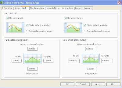
The Profile View Style dialog box has been enhanced with the addition of a new tab.
The Grid tab enables you to control grid clipping, grid padding, and axis offsets.
The Grid tab is shown in the illustration below.
At this time I’m going to talk about multiple profile creation, this option is new in the 2008 version and allows you to create multiple profiles at the same time. I’m going to walk you through for this new option.
Using the Profile View Wizard
A new and easy to use wizard, illustrated below, guides you through the process of creating either single or multiple profile views.
Use the wizard to:- Specify basic information about the profile view, including the parent alignment and the profile view name, description, style, and layer.
- Specify the station range to which the profile view will be drawn.
- Specify the profile view height and any split profile view settings.
- View and change settings for all the profiles associated with the specified alignment.
- Specify which pipe networks or parts to include in the profile view.
- The illustration below shows the next screen of the wizard.

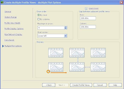
When creating multiple profile views, an additional step is provided to specify the layout of the plotted profile view segments.
Multiple profile views are most useful when you are creating final construction documents from your design. For best results, design your profile in a single profile view, then use the Plan Production Tools to create multiple profile views for plotting.
Using Profile View Styles
The Profile View Style dialog box has been enhanced with the addition of a new tab.
The Grid tab enables you to control grid clipping, grid padding, and axis offsets.
The Grid tab is shown in the illustration below.
You define settings in the Profile View Style Graph that specify the vertical exaggeration and the profile view direction.
Split Profiles
New to Civil 3D 2008 is the ability to create split profiles that fit within a specified profile view height. You can display the profile in either single or multiple profile views. You can use the Profile View Properties > Elevations tab to specify the elevation range of the profile view. If the profile view is split, you can use this tab to specify the stations and styles for the split segments.
Wednesday, July 11, 2007

Subscribe to:
Posts (Atom)


